Basic Electric and Ngspice Simulation
I want to be able to create schematics in Electric and be able to export those to spice files which can then be simulated. On Windows I can use Electric and LTspice to do this, but how can it be done on Linux where LTspice is hard to come by?
By using Ngspice as the circuit simulator! I might also be able to directly include the spice models for the nmos and pmos transistors from the skywater pdk to get something very close to what actually might be fabricated on that process.
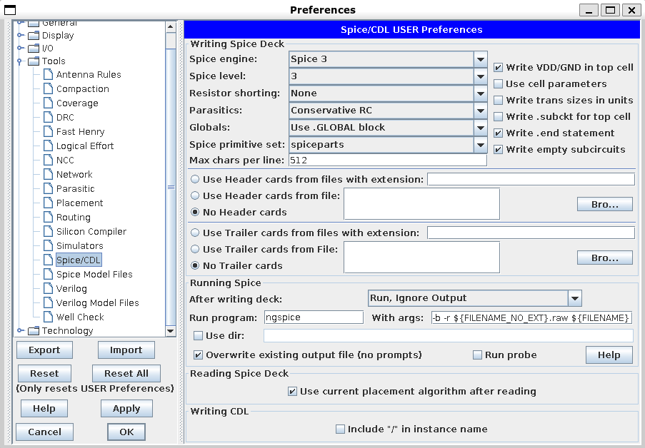
To get Electric to export something that can be read in Ngspice, go to File -> Preferences, then Tools-> Spice/CDL.
Change the spice engine to Spice 3.
In the running spice section, set “After writing deck:” to “Run, Ignore Output”.
Set “Run program:” to Ngspice
Set “With args:” to -b -r ${FILENAME_NO_EXT}.raw ${FILENAME}
The final result should look the same as below.
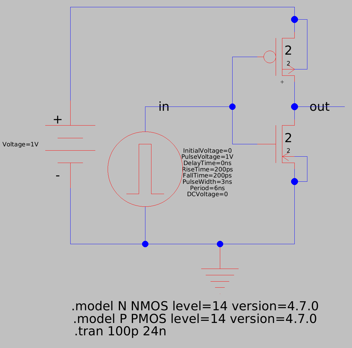
After doing this, build your circuit. Make sure that you use spice sources for voltage sources. I build a simple mosfet inverter which is shown below.
You will also need to add some spice directives for the simulation.
.tran 100p 24n runs a transient simulation for 24ns with 100ps timesteps.
.model N NMOS level=14 version=4.7.0 and .model P PMOS level=14 version=4.7.0 use the builtin nmos and pmos models as specified in the Ngspice manual. These are using the BSIM4v7 mosfet model.
Now to run the simulation, go to Tools -> Simulation (Spice) -> Write Spice Deck… This will run Ngspice and generated a .raw file.
To view the output of the simulation, any waveform viewer can be used. For just the basics, run Ngspice and then load the output data with load {YOUR_FILENAME}.raw. Then you can do plot {NET_NAME} {ANOTHER_NET_NAME} to plot any of the nets in your design.
In my inverter example, when I load the .raw file, I can do plot in out and get the following plot.
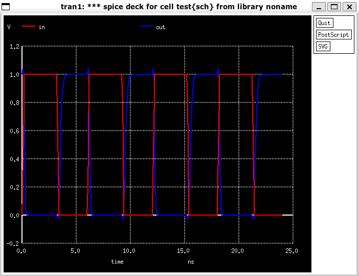
As you can see, the inverter is functioning as designed!